IC-7300 Additions
I find the IC-7300 quite a nice radio and certainly good value for money. This radio has an SDR architecture, a really nice waterfall display and a built in USB soundcard.
But there are a couple of features that I sorely miss. So this is my attempt to add in a couple of the features that I dearly would have liked to see in the radio.

Before reading any further, I must emphasise:
- Modify your radio at your own risk - and void the warranty.
- Pay attention to detail - mistakes can be costly.
- I offer these ideas for anyone who might be interested in emulating them. If you do not feel confident working inside your shiny new radio, then don't.
- I am happy to field any questions that you might have, but I bear no responsibility for what you do with your radio.
With that being said, here are a couple of additions that I have found useful to the radio
External PTT De-Assert Delay
The IC-7300 is infamous for having a firmware bug: The external PTT line is released (de-asserted) before RF energy ceases. This is usually not a problem if
 This bug is real and affects every IC-7300. The screen capture above shows the issue: The tail end of a CW character is captured. Channel 1 (yellow trace) shows the PTT line signalling from the IC-7300. Channel 2 (green) shows the RF envelope. I have set the CW rise and fall times to 8 msec in firmware to avoid key clicks. The radio is set for full break-in mode.
It baffles me why ICOM won't just fix this in software. It would take but a change of a few lines of code, if that.
This bug is real and affects every IC-7300. The screen capture above shows the issue: The tail end of a CW character is captured. Channel 1 (yellow trace) shows the PTT line signalling from the IC-7300. Channel 2 (green) shows the RF envelope. I have set the CW rise and fall times to 8 msec in firmware to avoid key clicks. The radio is set for full break-in mode.
It baffles me why ICOM won't just fix this in software. It would take but a change of a few lines of code, if that.
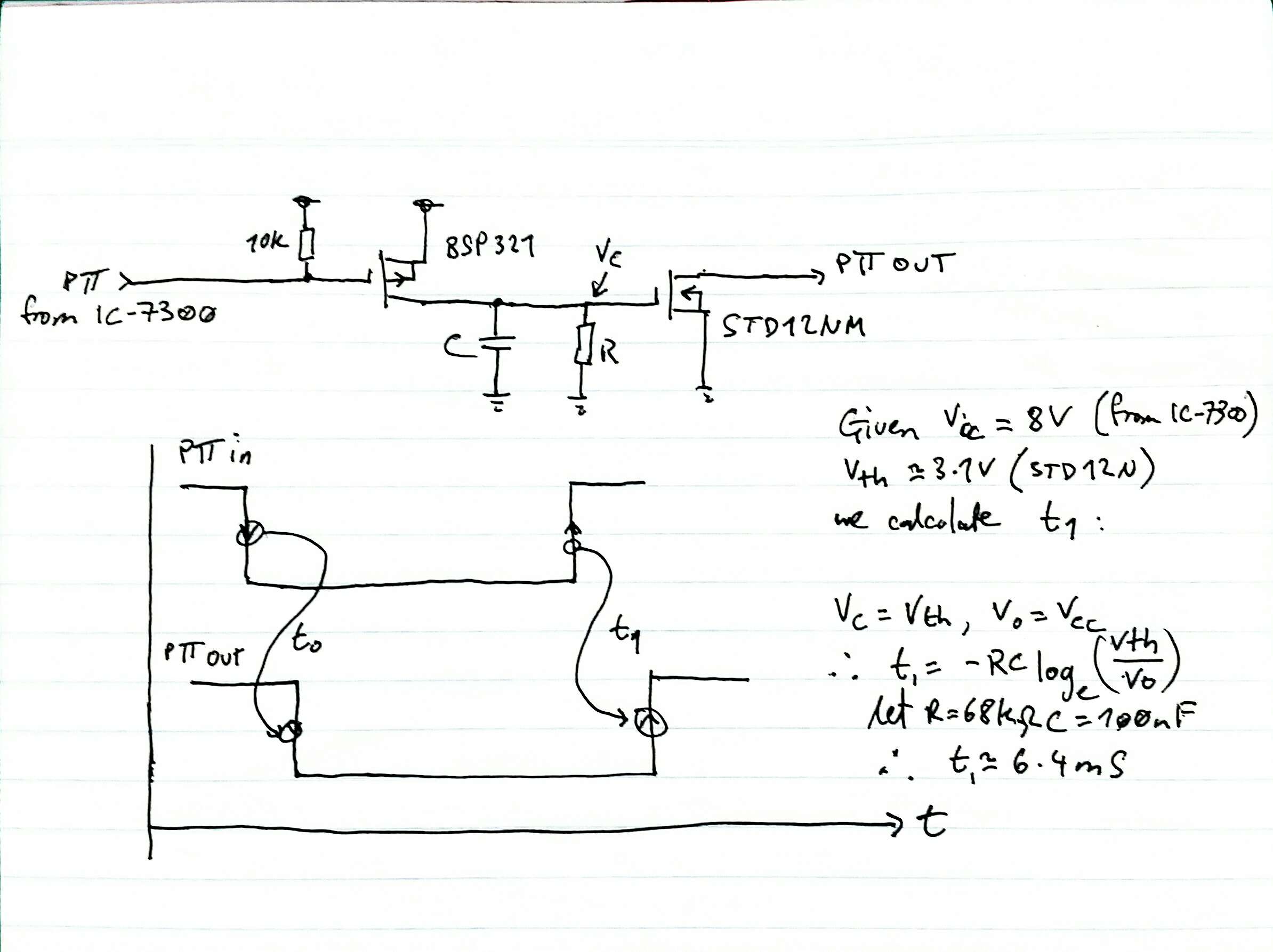
So without access to the radio firmware, a simple hardware pulse strecher is the answer. There are a few versions available on the web.  I chose a simple 2 FET solution as it is small, doesn't load the radio's PTT line and I can use a higher voltage and current rated FET to signal PTT to external equipment.
It was not worth even drawing up a proper circuit, so here is my hand-drawn scribble. I had the FETs on hand. Nothing really special required. Just make sure that the N-type that you select will be able to handle the current and voltage requirements that you need to switch down-stream.
I chose a simple 2 FET solution as it is small, doesn't load the radio's PTT line and I can use a higher voltage and current rated FET to signal PTT to external equipment.
It was not worth even drawing up a proper circuit, so here is my hand-drawn scribble. I had the FETs on hand. Nothing really special required. Just make sure that the N-type that you select will be able to handle the current and voltage requirements that you need to switch down-stream.  I calculate a PTT assert "stretch" of around 6.4 msec. I measured a stretch of 6 msec, meaning this circuit will hold the PTT asserted for an extra 6 msec after the IC-7300 de-asserts the PTT line. This should give me a 2 msec safety margin. The assert time delay (the start of PTT) of this circuit measured at around 8 usec - plenty fast enough!
Does it work? Yes. Very well. I see a full 2 msec delay between the RF envelope disappearing and the IC-7300 PTT line deasserting. It works beautifully with QSK CW, and the assert delay is completely insignificant. All this, but for the want of a sign change in a variable of firmware code...
Automatic Antenna Switch
The IC-7300 covers all the HF bands, as well as 6m. But it has only one antenna output. I certainly do not have one antenna to cover all these frequencies so an external antenna switch is more or less mandatory for me.  But being lazy and forgetful, I find myself more often than not transmitting into the wrong antenna. Not a big deal as the radio has a VSWR shut-down, but annoying none the less.
So I thought it a good idea to make up an automatic antenna switch, to change antennas based on the radio dial frequency. This is not a new idea and can be done relatively easily by reading the CI-V port data (from the Remote port on the back of the radio) then switching an appropriate relay to connect an antenna of choice. On the left you can see the control unit for the automatic antenna switch sitting on top of the IC-7300. This little project divides neatly into 2 parts:
- A microcontroller to read the CI-V data from the radio and handle the switching logic.
- A relay switch unit to switch over the RF.
The control unit is quite simple, so no custom PCB was made. Instead I used some veroboard to wire everything together. I chose to use an ATMEGA16 as I has some on hand.
 The ATMEGA16 handles the following:
- Read the pushbutton switches on the front panel to select an appropriate antenna port for each band.
- Decode frequency data from the CI-V port of the radio.
- Switch the correct relay.
- Maintain a look-up table of antenna port selection for each band.
There is some effort put into switch de-bouncing as well as ensuring that the microcontroller goes into SLEEP mode when it is not required to do anything. In this way any RFI is eliminated.
 Ultimately it all fits nicely into an extruded aluminium box with a minimum of fuss. The unit is powered from the radio via the External ATU connector, and draws less than 50mA of current.
Likewise, the relay box is also simple. I chose to use SPDT relays so as to short-circuit the unused antennas.
 The relays are wired dead-bug style into a diecast aluminum enclosure. Some effort was made to improve shielding between ports, although that is hardly necessary at these frequencies.
An added side benefit of this project is that I can now mount the relay box externally and run a single coax and control cable back to the radio. This has helped tidy up the mess of cables that seem to infest every ham radio install that I have ever seen.
The relays are wired dead-bug style into a diecast aluminum enclosure. Some effort was made to improve shielding between ports, although that is hardly necessary at these frequencies.
An added side benefit of this project is that I can now mount the relay box externally and run a single coax and control cable back to the radio. This has helped tidy up the mess of cables that seem to infest every ham radio install that I have ever seen.
In operation, all you need do is select one of 4 antennas from the front panel switch. The microcontroller then switches the appropriate relay as well as writing your selection to an internal EEPROM look-up table. Whenever you return to the same band your previously stored antenna selection is set.
As this was a quick one-off weekend project, no proper schematic was drawn. If there is enough interest in this project from others I may be persuaded to draw up a proper schematic or even get a small run of PCBs manufactured.
Auxiliary RX Antenna
The next item on the IC-7300 wish list for me would be a dedicated receive-only antenna port. This would allow splitting TX and RX antennas, since in general we tend to optimise different metrics: for transmit we obviously want to maximise radiation efficiency whereas for receive we would want to optimise signal to noise ratio.

Fortunately, the IC-7300 provides a most convenient spot to achieve this without too much internal modification required. An extract from the user manual shows the RX signal is routed from the main antenna via the PA unit to the RF Unit via coaxial jumper WX (RXRF). All that needs to be done is for a relay to switch J1071 between J801 (the main TX/RX antenna) and a separate external RX antenna port.
To keep things neat and tidy I made up a small PCB with the appropriate relay switching and some basic protection against large signals. The PCB is shaped to allow it to slot into the space normally reserved for the External ATU connector. The entire addition requires no cutting of wires or soldering to the radio.
 Only one screw on the RF Unit need be replaced with a stand-off. Best of all the External ATU connector can still be used.
To enable the Auxiliary RX antenna the SW port is shorted via an externally mounted switch.
 It would be nice if the radio firmware could be hacked to provide a touch-screen button for this, but I doubt that ICOM will be releasing their firmware anytime soon.
The PCB protrudes just far enough behind the rear case to permit mounting of an SMA connector
(for the auxiliary RX antenna), an RCA connector  (for the switch) and a 4 pin Molex connector which can be used to reconnect the original ICOM External ATU wiring loom.
I also decided to have a quick look at the RF performance of this switch. The insertion loss is respectable (better than 0.1dB @ 54MHz) and the isolation is likewise acceptable (better than 65dB @ 54MHz). In all a reasonable result for such a simple design.
I have some PCBs and enough components  left over to make up a few more units.
If you are interested in making the same mod to your IC-7300, drop me an email.
left over to make up a few more units.
If you are interested in making the same mod to your IC-7300, drop me an email.